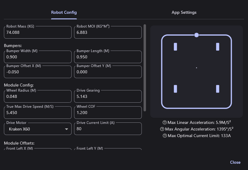
Robot Config
Both the GUI and PathPlannerLib require various configuration options to be set in order to generate trajectories that are accurately limited for the performance of your robot. All of these values have an effect on the performance of your robot, determining its maximum velocity, acceleration, etc. Therefore, you should take care to ensure that these options are configured as accurately as possible.

Robot Config Options
- Robot Mass
The mass of the robot, including bumpers and battery, in Kilograms. In most cases, choosing the maximum robot weight of ~68 KG (150 lbs) will work fine. However, lightweight robots may benefit from increased acceleration and better friction estimates if the robot mass is measured accurately.
- Robot MOI
The Moment of Inertia, or MOI, of the robot, including battery and bumpers. This can be calculated via CAD software, or measured in various ways.
Calculating MOI through sysID (Recommended)
Once sysID has been performed, the robot's MOI can be calculated using the following formula:
Where
Calculating a Rough MOI Estimate
The robot's MOI can be roughly estimated using the following formula:
However, this will likely lead to an inaccurate estimate as it assumes a uniform distribution of mass.
- Trackwidth
The distance between the left and right sides of the drivebase, in meters. Only available for non-holonomic robots.
Bumper Config Options
The following options are only for visualization purposes in the PathPlanner GUI and are not used in PathPlannerLib.
- Bumper Width
The width of the robot's bumpers, in meters.
- Bumper Length
The length of the robot's bumpers, in meters.
- Bumper Offset X
How far the center of the bumpers are offset from the center of the robot along its X axis, in meters. Positive values indicate the center of the bumpers is forward of the robot's center.
- Bumper Offset Y
How far the center of the bumpers are offset from the center of the robot along its Y axis, in meters. Positive values indicate the center of the bumpers is left of the robot's center.
Module Config Options
- Wheel Radius
The radius of the drive wheels, in meters. This should be listed wherever you buy your wheels from, but can also be measured.
- Drive Gearing
The gear reduction from the motors to the wheels. Since this is a reduction, this value should be greater than 1. For example, the gearing of an SDS MK4i module with L3 gearing is ~6.12
- True Max Drive Speed
The true maximum speed of the robot/drive module while driving under load, in meters/second.
- Wheel COF
The coefficient of friction between the drive wheels and the carpet. Some wheels will have their COF listed on their store page. The COF of friction can also be calculated by measuring how much force is required to pull the robot ( causing the wheels to slide) across the carpet. You can also tune this number until the wheels no longer slip while accelerating or turning in corners.
- Drive Motor
The type of motor used to drive the wheels of the robot.
- Drive Current Limit
The supply current limit applied to the drive motor controllers, in Amps.
Module Offsets
The locations of each swerve module relative to the center of the robot, in meters. These should be the same offsets used to create your kinematics in code. Only available for swerve drive robots.
Robot Features
Robot features are shapes that can be added to the robot in the GUI. These can be used to represent intakes, shooting trajectories, etc. Current features include: rectangle, circle, and lines.